Installing Marlin on the Sapphire Pro
updated 19 Jan 2020
The Marlin contributors have updated the config files on the repo to include changes for the upcoming release and, as such, they are not compatible with 2.0.7.2. Download the archived versions of the config files from my site to get it working. When the next release comes out, I will change this procedure again to fit.
This is the process of how I installed Marlin 2.x on the Sapphire Pro in Nov 2020. Since the Marlin source code is ever-changing, I would consult their repo or website before attempting this procedure.
For reference, I have never used Marlin, Microsoft VS studio, or uploaded firmware before. So there are bound to be errors and improvements.
I have archived the config files that I used on my website. Download the config.h and config_adv.h files here. I encourage you to use the latest from github, however.
Download the latest release of Marlin (2.0.7.2).
Replace the example config files with your Sapphire Pro specific Configuration.h and Configuration_adv.h files in the ../Marlin-2.0.x/Marlin/ folder.
Install Microsoft Visual Studio Code using the .deb package for ubuntu. I would have used the FOSS Arduino IDE, but it doesn’t support the STM32F103 chip.
Install the AutoBuild Marlin extension for VS Code by pasting the ext install MarlinFirmware.auto-build command into the quick open prompt (activated by pressing Ctrl+p).
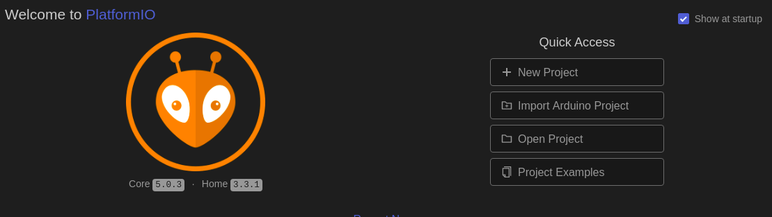
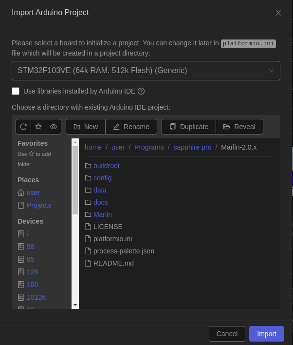
After a restart and quick settings change to disable Microsoft from collecting data on you, import the marlin source code folder using the PlatformIO panel “Import Arduino Project” button from the quick access panel.
Search for a STM32F103VE chip and locate the Marlin-2.0.x release folder you downloaded earlier.
Click the Marlin AutoBuild tab and build the firmware by clicking the hammer icon.
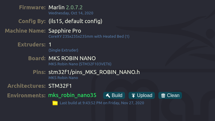
Grab the firmware binary at ../Marlin-2.0.x/.pio/build/mks_robin_nano35.bin and transfer it to a SD card. When inserted into the Sapphire Pro, the bootloader on the Robin Nano automatically installs the new firmware.
And there you have it folks: Marlin 2.0 on the MKS Robin Nano 1.2 in a Sapphire Pro.
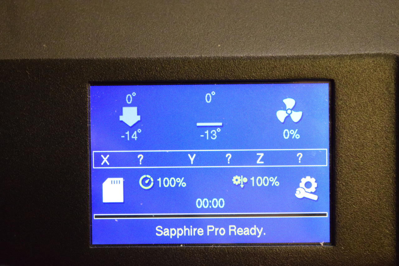
Don’t mind the negative temperature values. The sensors aren’t connected to the board yet.
Work Log
TODO
- [ ]
19 Jul 2021
Welp. I’m stupid. I thought a roll of PETG was PLA. No wonder that I was having trouble printing with it. This may have been the source of the problems I have been facing over the last few months.
01 Jul 2021
Printer has been down since Feb. Bought new nozzles, lost in the mail, reshipped, lost in my house, installed, failed.
I think the tiny hotend just can’t handle the poor thermal conductivity of steel nozzles. I’m just going to order a few brass nozzles from China and move on to better builds.
I’m looking into a better design, namely, Voron.
The V2.4 seems like the best option for me. They even have a “PrintItForward” service for newbs who can’t print ABS (like me).
I submitted a request on the PIF service. By the current fulfillment rate, I’ll get the parts in a few months.
I’ll just slowly accumulate the other pieces in the meantime.
16 Feb 2021
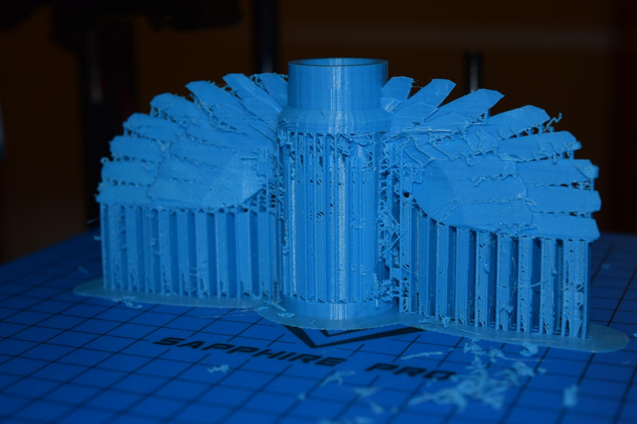
The printer is down for the count. After several failed attempts at printing a (+450g) cooling jacket, I have determined that the nozzle is screwed. Or the block. Or just the PTFE tube. Or something else. Idk. The Sapphire pro was worth every penny of that $325 purchase price…
I’m definitely looking forward to assembling a better quality printer. Like the SK-GO 2 or one of the LayerFused designs.
19 JAN 2021
I updated the marlin installation instructions. Instead of relying on the Marlin repo to maintain current, working versions of the config files, I simply backed up copies on my website.
10 DEC 2020
I’m know now why the Sapphire Pro is so cheap. While attempting to repair one of the broken solder joints on a blower fan, the board trace broke off. So now I have to buy new fans. This combined with the poor solder joints on the endstop switches and the broken temperature sensor leads me to believe that some corners were cut. Go figure…
05 Dec 2020
Boron nitride is used as a high-temperature, electrical insulating thermal “paste”. An aqueous suspension of hexagonal BN is applied to thermistors, heaters, etc.. When heat is applied, the water evaporates leaving a white semi-solid.
30 Nov 2020
I found a 600C thermistor. EPCOS B57650H0824A001 (datasheet). It only costs $7.41 which is comparable to the standard 100K B57540G0104F000 at $6.33
It is listed on digikey as a “5K Ohm” NTC thermistor, but that’s actually the resistance at 200C. Remember to check your datasheets people!.
The datasheet for the chip that drives the MKS Robin Nano v1.2 (STM32F103VE) shows that it uses 12-bit ADCs. That’s 4096 values.
The value of an RTD is measured using a resistance voltage divider circuit.
\(V_{RTD} = {R_{RTD} \over R_{pullup} + R_{RTD}} V_{in}\)
The voltage that is measured by the ADC is a function of the pullup resistance (typically 4.7 kOhm), the input reference voltage, and the RTD resistance.
I know that my board uses 3.3V input based on the product information page, which is typical for ARM chips. Some TTL chips use up to 5V.
So the full range of values that the ADC can represent has a voltage discrimination of 0.8mV (3.3/4096).

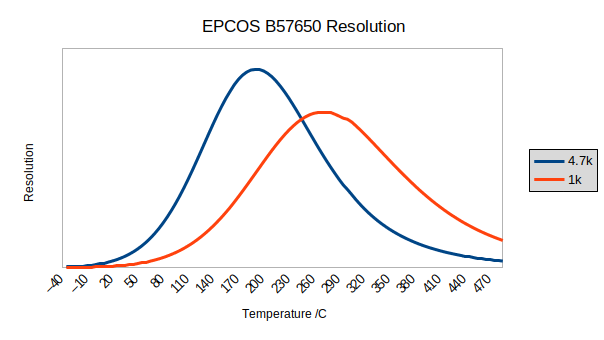
So as you can see, the resolution (higher is better) peaks around 200C which is almost perfect for PLA printing. You can shift the resolution curve by changing the pull up resistance value at the expense of lower peak resolution.
If you are planning on doing the majority of your printing above 250C, I would recommend changing the pull up resistance.
| Average Resolution | ||
|---|---|---|
| Temp Range | 4.7K | 1K |
| 200-250C | 95 | 72 |
| 250-300C | 57 | 84 |
The resolution of each range given a pull up resistance value of 4.7K ohm or 1K ohm. higher is better
You can download the spreadsheet used to make the graph.
I did not include the actual values in the graph since that would give the wrong impression. This thermistor has a standard 2% resistance error and a 1% beta error. The resistance value also has a variable deviation from ideal with temperature. Regardless, we are talking about resolution not accuracy. Plus, I’m not sure if I even did the calculation correctly. But the shape of the curve should be adequate for demonstration purposes.
The Robin nano also features a MAX31855 Thermocouple to digital converter. I don’t think I will buy a thermocouple at the moment but mostly because I have a few k-type thermocouples already that I can use for testing.
I’m going to buy some other 100K NTC themistors (Littlefuse 104JL1A). They are cheap and appear to be quite accurate. And we will throw a few NB-PTCO-029 PT100 platinum RTDs on there as well.
I really don’t think we have to worry about the response time of the sensing element. Most hotends have a standard 3mm stainless steel cartridge insert. The thermal resistance of the steel and filler will probably be of greater impact than the sensor itself.
Some info on characterizing RTDs.
To directly interface with my Robin nano, I need a RTD to voltage converter. A paper from TI on a RTD to voltage circuit, and a similar document from Microchip. Adafruit has a RTD to digital breakout board based on the MAX31865 chip.
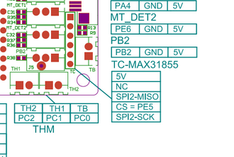
Oddly enough, there appears to be parts of a SPI connection on the Robin nano.

You can see the SPI2-MISO and SPI2-SCK connections listed under the thermocouple measuring header but no mention of MOSI or SS. So maybe the SPI interface of the MAX31855 is exposed for who know what reason? It might be possible to interface with the ARM chip through these connections or even bit bang the SPI interface on one of the other connectors, but I don’t think it is worth it. Time would be better served by starting with a better board.
On a completely different note, connectors are really hard to find when you don’t know exactly what you are looking for.
For the record, the connectors that are typically found on DIY circuit boards, stepper motors, and most things 3D, are the (I think) XH headers, XHP housings, and SXH sockets from JST Sales America Inc. XH Series Datasheet
I’m a little confused. The official JST website says that the XH-style connector has a 2.5mm pitch. NOT 2.54. Yet just about every reseller advertises the XH connector as 2.54mm. Even Adafruit, which even includes a link to the same JST page I just did.
PH headers, PHR housings, and SPH sockets are also common.
28 Nov 2020
This leaves me with choosing a proper hotend thermal measuring device. Most hobby 3D printers use NTC thermistors. Some of them are in a stainless steel capsule for protection and interchangeability.
For some background, Marlin has a detailed temperature sensors section, RepRap has a good wiki on thermistors, and Dyze Design has a detailed comparison
27 Nov 2020
So the hotend thermistor (?) is broken on the 3d printer. I disassembled the entire printer in order to 1) repack the linear bearings, 2) fix the hot end thermistor, 3) fix cable routing, and 4) enclose the print area.
My goal is to be able to print higher temperature materials, specifically polycarbonate.
The problem, however, is that I have no idea what thermistor is used in the stock hotend. The thermistor attached to the print bed seems to be around 100K Ohm. The TwoTrees website (edit they do now) doesn’t sell replacement thermistors or have any information on them. There are a few replacements advertised on banggood and aliexpress, but there are all different and all claim to fit the sapphire pro.
So now I have to either take a guess at the thermistor value gamble that it is correct, or I can install my own firmware. I’m going to go with the latter.
Marlin seems to be a good choice.
After much debugging, I found a way. It is detailed above.
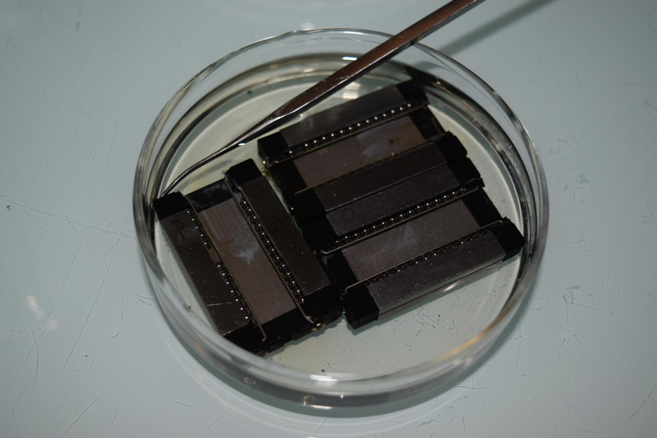
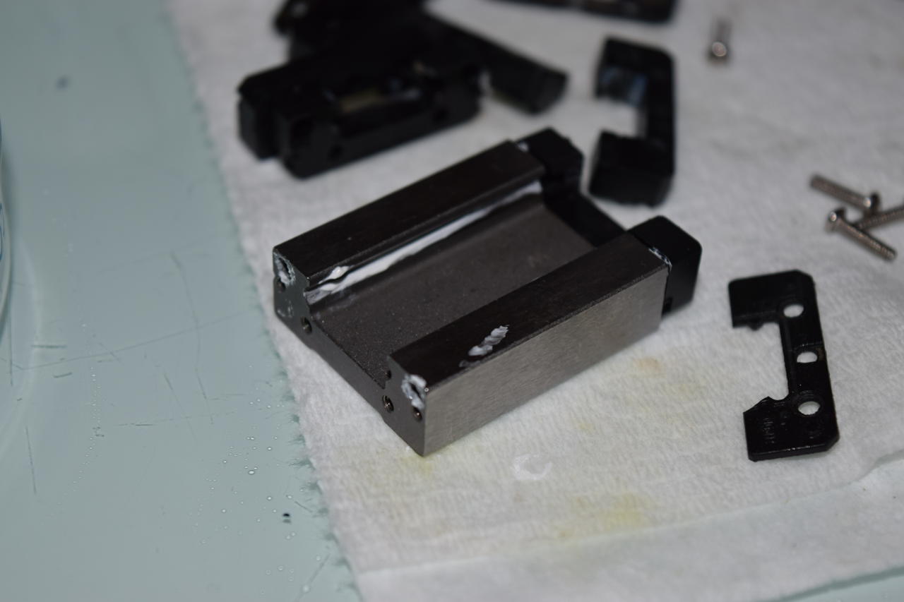
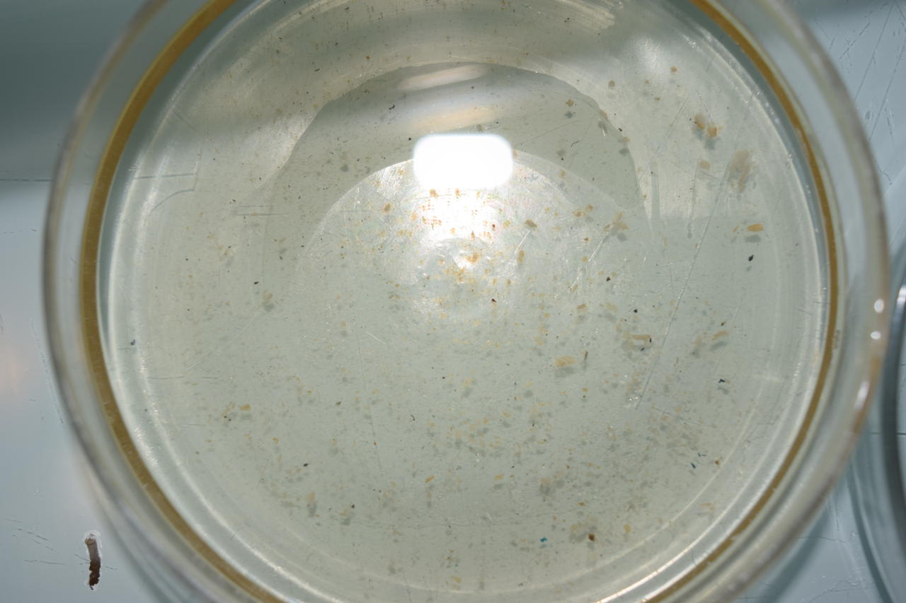
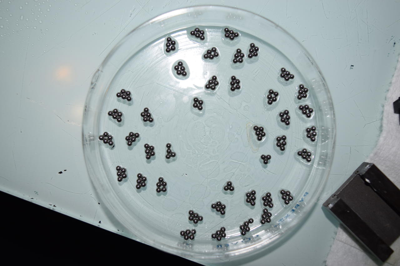
I also disassembled, cleaned, and repacked the linear bearings.
The ball bearings were 0.087" or 2.2mm in diameter.
25 Oct 2020
The 3D printer is assembled. It went together smoothly and relatively easily. I probably spend more time cable managing than assembling.
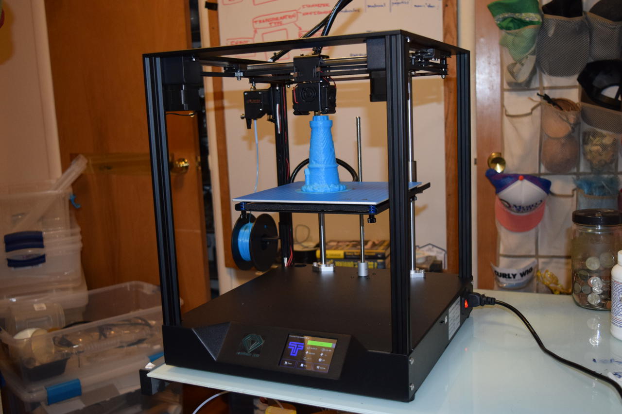
Just in time, too. I wanted to print a time-flies hourglass cane topper for my plague doctor costume for Halloween.
The 200g filament spool that came with the machine is pretty terrible. It tends to break in the middle of a print and it leaves quite a few artifacts.
I ordered a couple kgs of cheap PLA from Amazon as a start.
21 Oct 2020
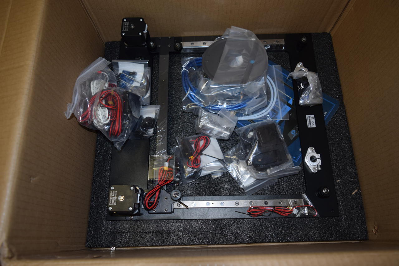
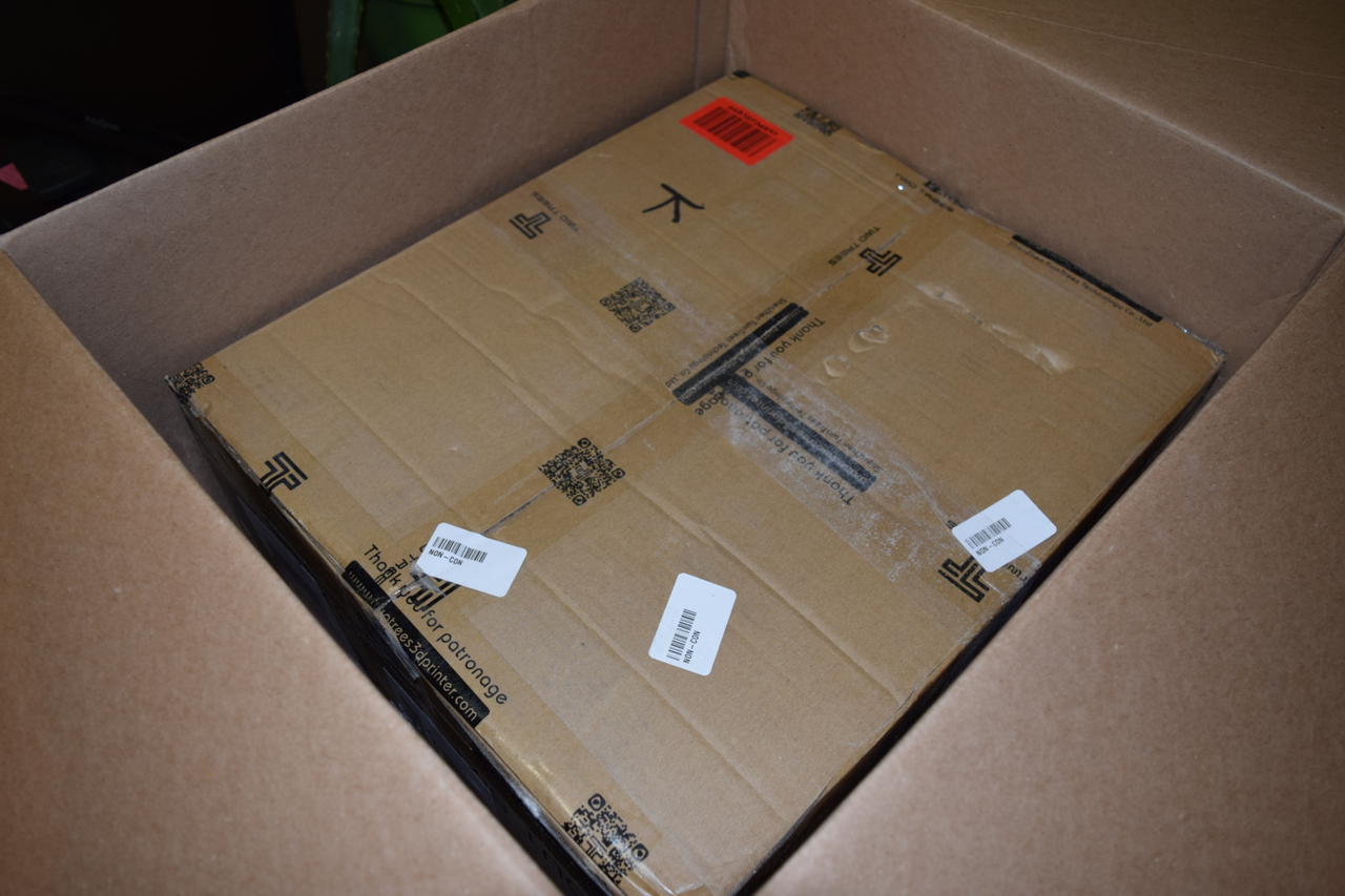
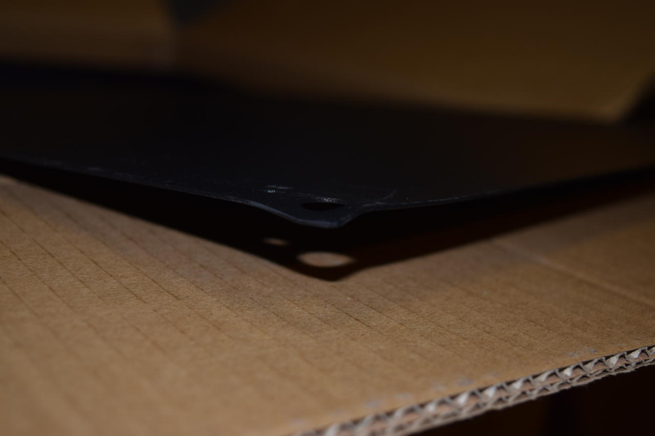
The printer arrived today. Wow that was fast.
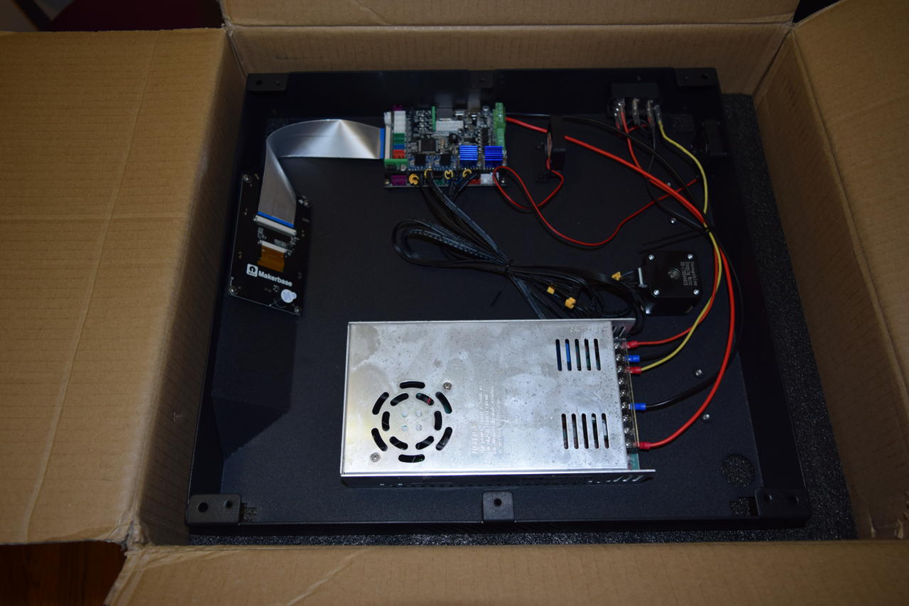
The only problem I had with the unboxing was that the bottom sheet metal cover was slightly bend on one corner.
19 Oct 2020
I bought a 3D printer today: TwoTrees Sapphire Pro.
28 Nov 2020
Project Created!