Again!
So I have picked up this project again circa 2018. My sister has asked me to look into making a small tesla coil for her haunted house. Enough to be scary but not too dangerous.
Design Parameters
- secondary
- height: min, max
- width: min, max
- wire_size: min, max
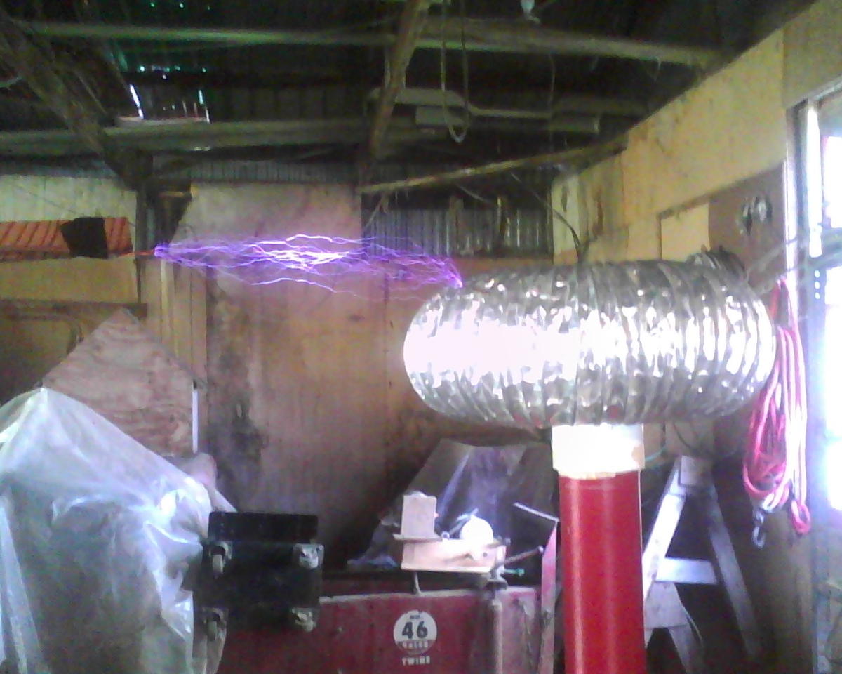
DRSSTC in Action
Work Log
TODO
- [ ] Order electronic components for new controller.
14 Oct 2018
I missed my deadline :(
10 Oct 2018
- interrupter work
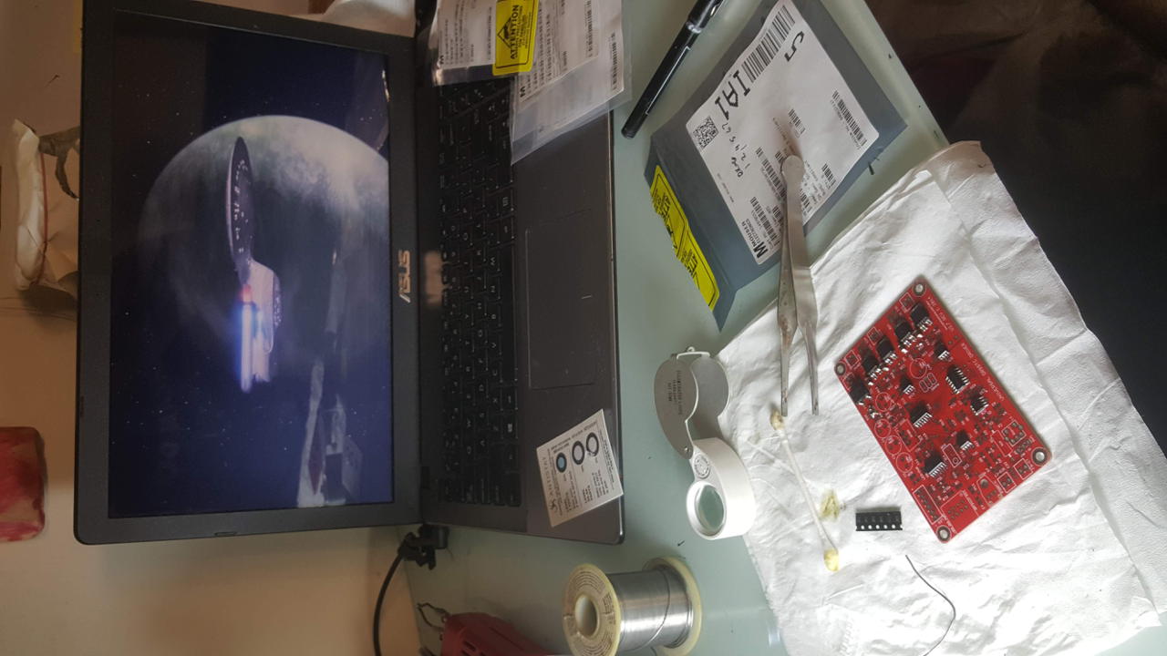
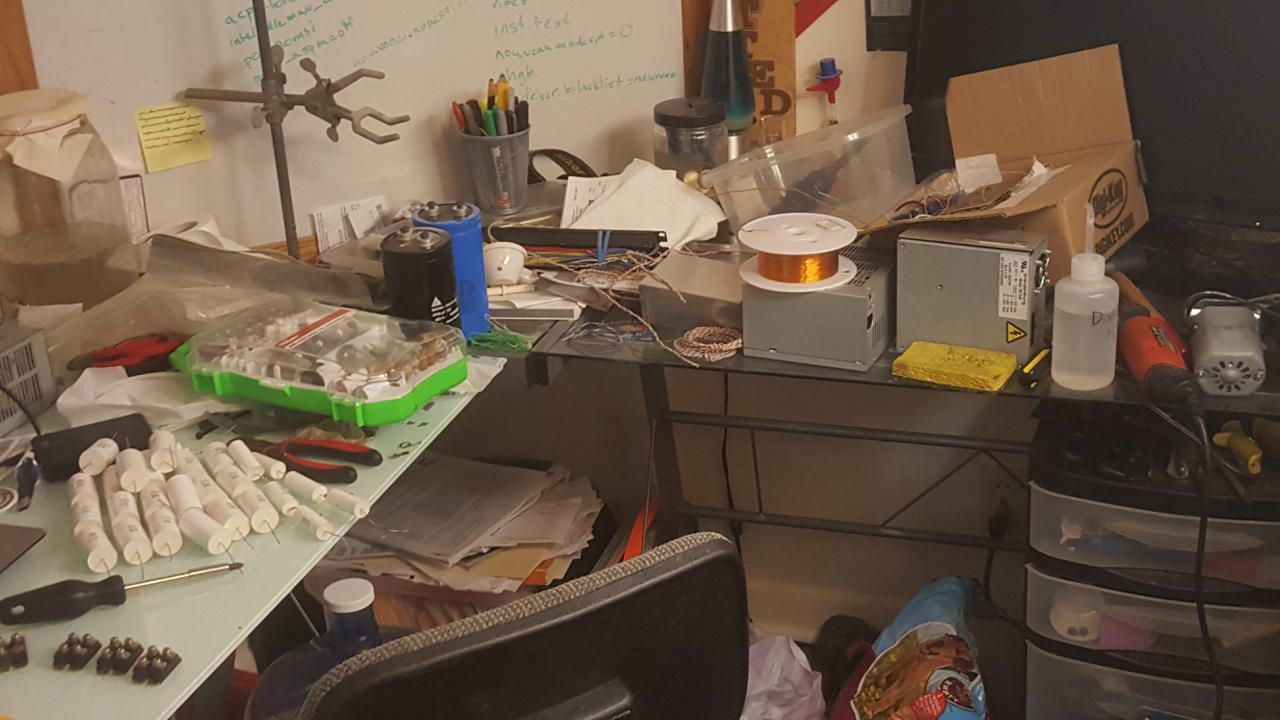
It gets a little messy around here when I’m this close to a deadline:
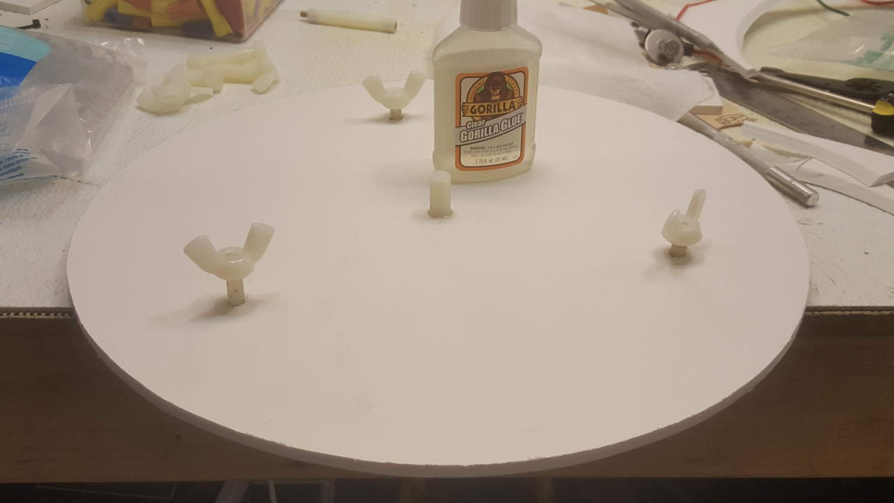
09 Oct 2018
- mostly framing work: using nylon bolts to attach various components together
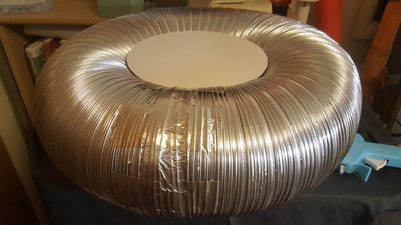
08 Oct 2018
Made a toroidal topload from 8" dryer duct wrapped in aluminum tape. I also have a 4" duct if I need more capacitance (probably).
Secondary coil has been wound and coated with 1/2 pint of polyurethane. I would have preferred to use epoxy, but I didn’t want to spend the extra $30
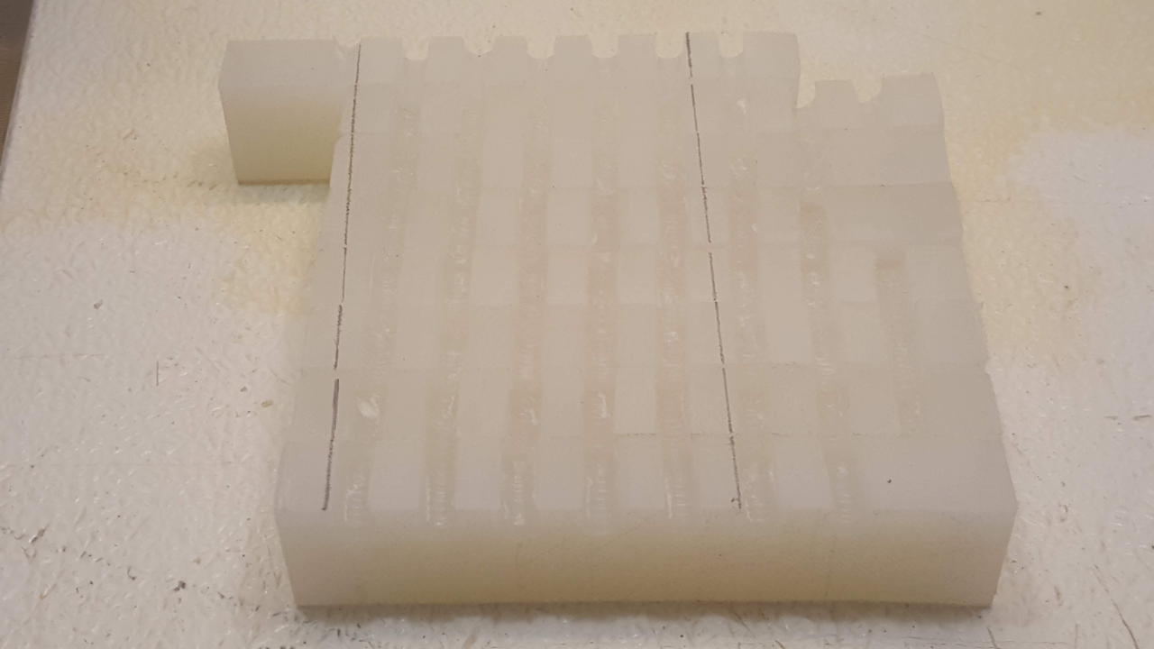
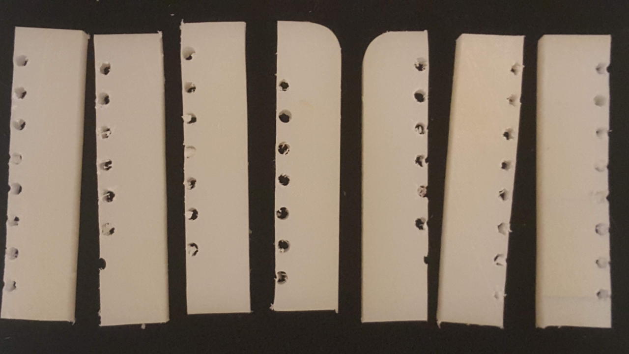
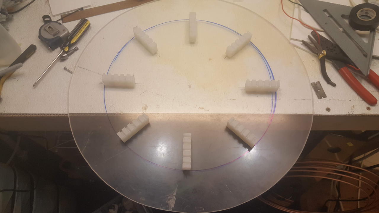
Primary coil supports were cut from 1/2" HDPE cutting board. 7/32 holes were drilled to accommodate the 1/4" annealed copper tube.
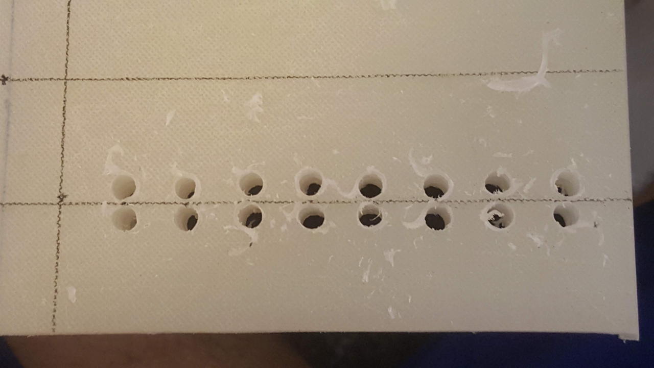
A polycarbonate circle was cut for the base of the primary coil.
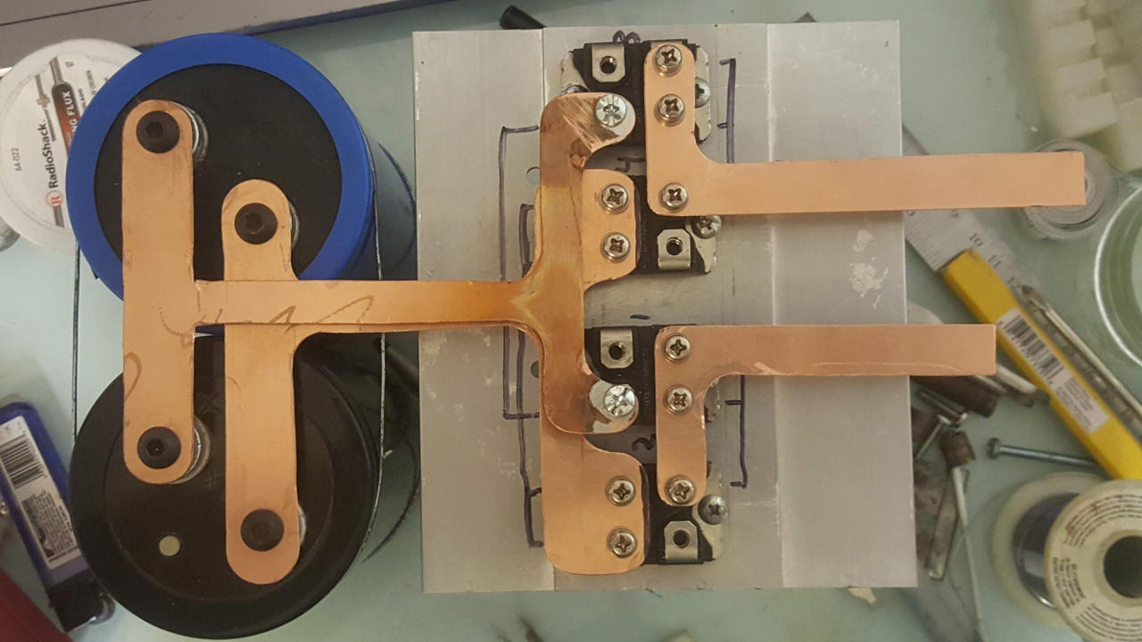
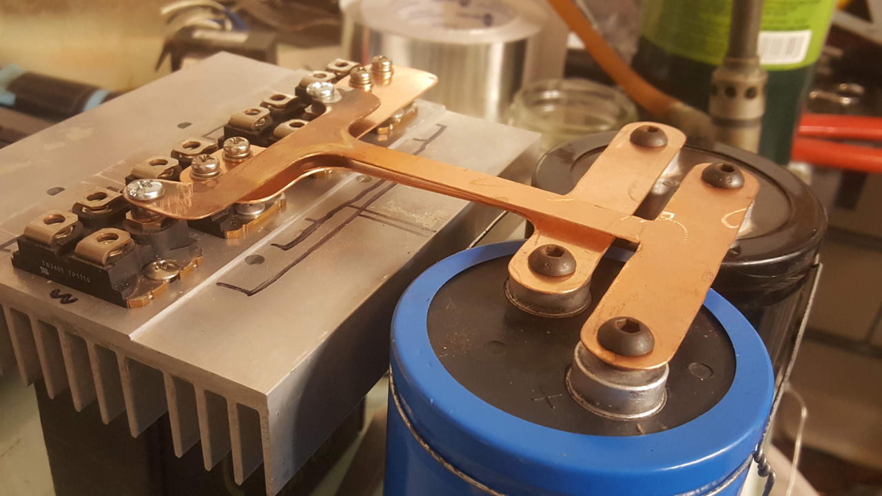
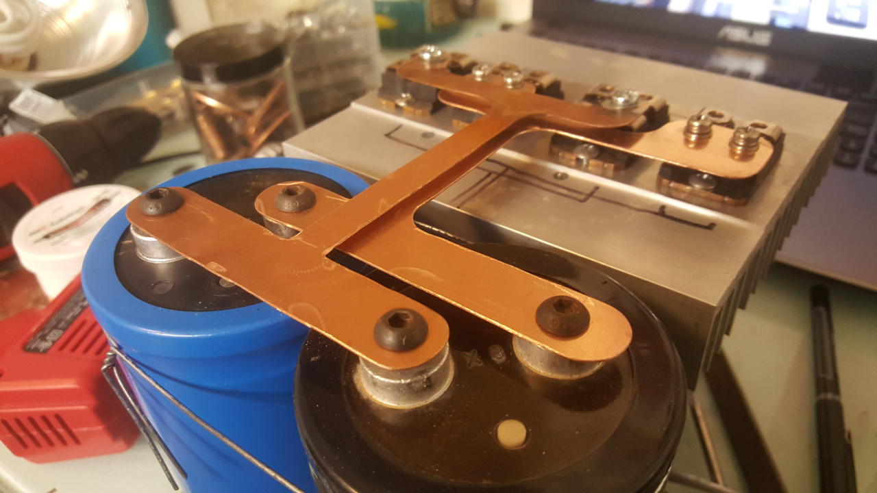
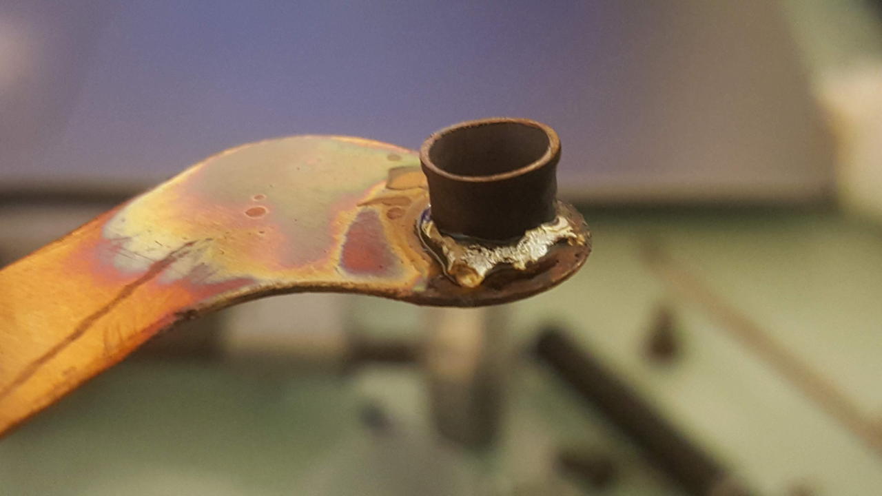
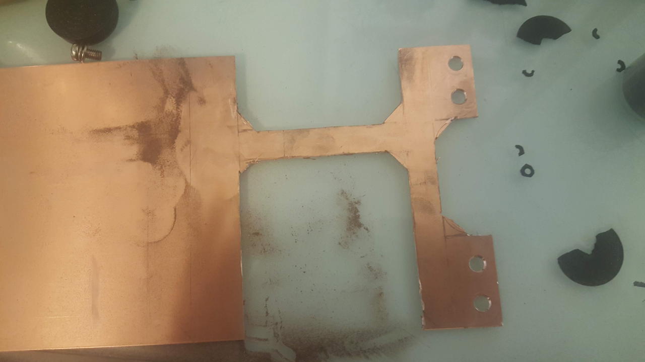
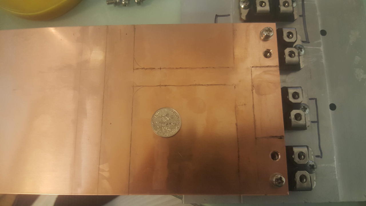
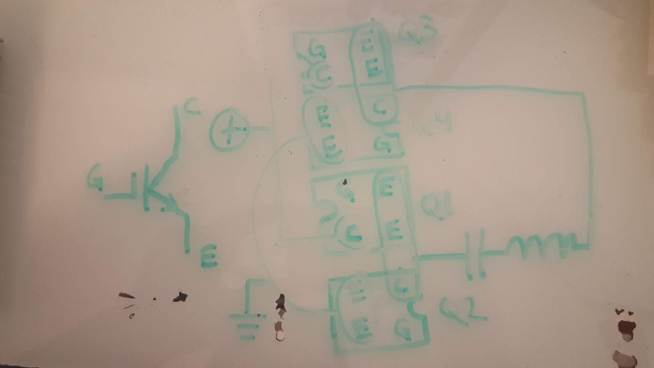
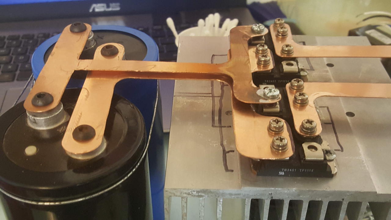
Copper bus bar was cut for the full bridge of IXG60n60’s. I’m a little worried that I cut the bus bar too small, but too late now. I configured the electrolytic capacitors in parallel: if I want a voltage doubler I will need to redo it.
21 Sep 2018
- attempted to make a cone out of paper
- 8" radius at low voltage end and 0.8" at high voltage end
- total height 20.25“; winding length 21.5”; ~2500feet of 26AWG double build magnet wire
- traced out a 123 degree arc at a radius of 23.4"
- unless you had many layers… not going to work
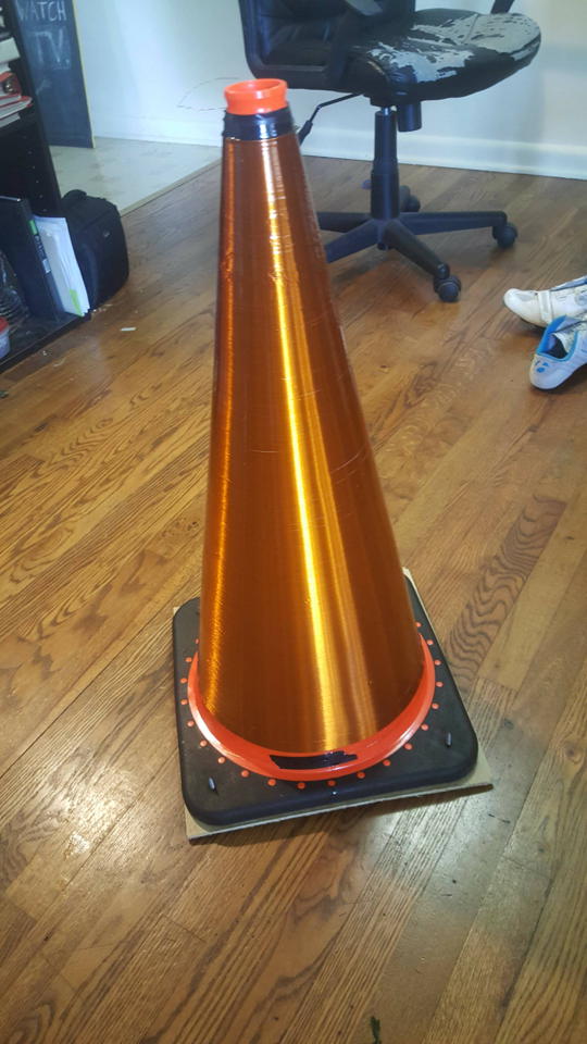
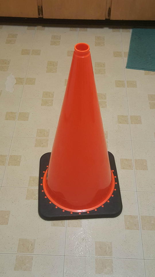
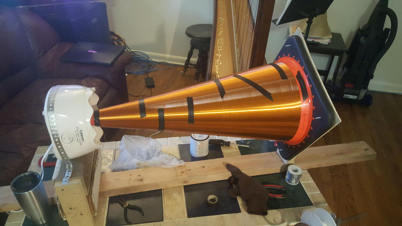
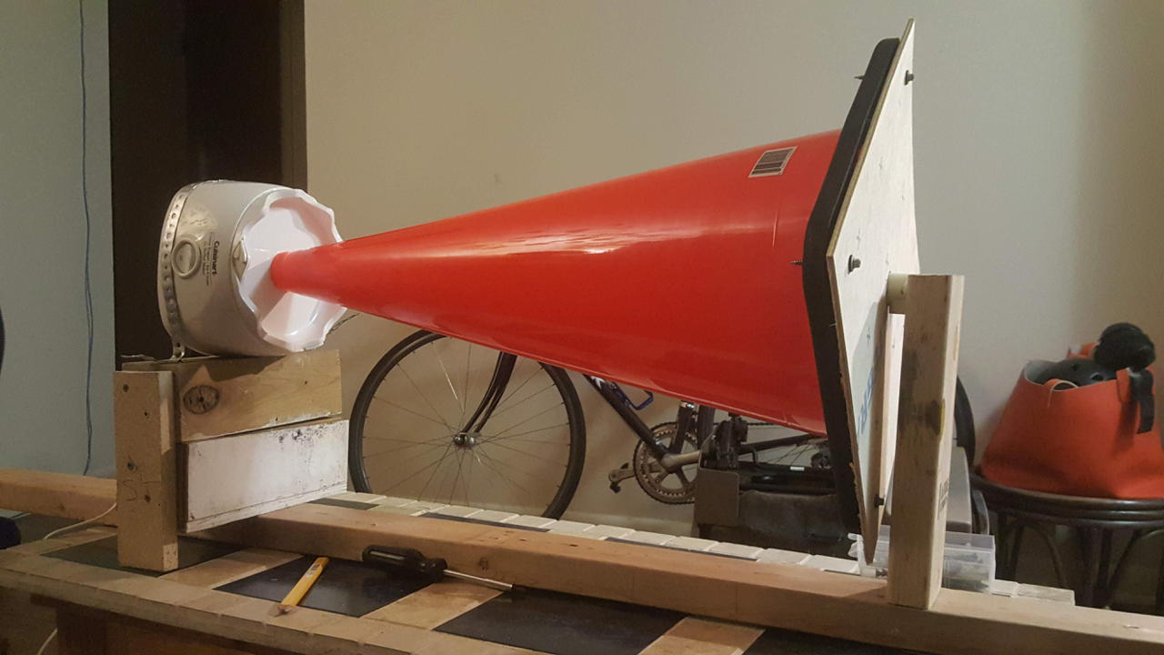
- I just bought a 27" traffic cone instead
- it is a little smaller than I was planning, but it will work
- now… to build a coil winding jig
- Finished the winding jig
- it just so happens that the small end of the traffic cone fits right into my ice cream maker’s gear: perfect
20 Sep 2018
- comparing the benefits of a conical secondary?
- one paper (Craven, Smith, and Novac 2017) suggests the reduced self capacitance of the coil is the primary benefit
- a smaller self-capacitance allows for a larger topload: decreasing stress on the coil and increasing breakout voltage for a given resonant frequency
26 Aug 2018
- about halfway through the simulations so far
- what diameter primary wire (tube) do I need?
- 1/4 soft copper tubing: 9.5mm outside diameter
- Copper tubing sizes
- at 100 KHz skin depth is \(\delta = ~0.21mm\)
- total area for current using 1/4 copper: \(D_{out} = 12mm^2\)
- \(A = \pi*(D_{out}^2 - (D_{out}-\delta)^2)\)
- Gives a max (power supply) current of around 35A -> Not large enough
- Wire gauge current limits
- max RMS current of my IGBTs (IXGN60N60) is 60A
- total area for current using 3/8" copper tubing: \(D_{out} = 16.4mm^2\)
- Max current = 47A… still not enough but I’m going to use it anyway. What’s a little resistive heating between friends?
- I’ll need at least 1,000 ft of secondary wire
- 20-30 AWG
- I would really like to have a formless secondary coil for less interturn capacitance and loss
- use a pvc form to wind it, epoxy it, then remove the form
- just a few end caps of thick material for mounting
- I have plenty of polycarbonate for making the electronics base and primary coil supports
- Teflon insulator between primary and secondary? Kapton?
- I have some kapton film somewhere.
- Kapton sells tape using a silicone adhesive
- I could wrap the bottom (and top?) of the secondary with a few layers of kapton using silicone as glue to prevent arcs
- Strike ring?
13 Aug 2018
- started work on modifying ScanTesla -> probably won’t finish it unless I have a lot more time
- evolutionary algorithms would be great here
- started ScanTesla running calculations: 146,257,650 simulations to go…
25 Jul 2013
Designing a Tesla Coil
I have been working on this for a few days now: trying to find formulas that define the best configuration of a tesla coil. While reading through the Colorado Springs Notes I saw a remark made by Tesla, “Now the secondary, to be at best, should work with all jars [capacitors] available and the regulating coil should be all cut out in the primary. This is namely the condition corresponding to the full output and the highest economy.” Tesla had to use an additional inductor in the tank circuit to tune the coil since he used a static, unadjustable primary. So anyway… I will keep a list here of basic design principles that may or may not be correct or up to date as I add to it:
- Higher inductance to resistance ratio results in a better performing coil. ie. L/R is proportional to Q.1[]
- Reduce parasitic capacitance in all coils.2[]
- Total length of any resonating circuit must be 1/4 of the wavelength of the standing wave in the material.
- Use the largest capacitance your power supply can handle.
- The ratio of inductances between primary and secondary (free resonator) determine the maximum voltage gain.
- The coil is meant to resonate: coupling is key.
And now some explanations on each point…
Obviously you should reduce resistance and increase inductance here. The problem is that they are inversely related. The more turns of wire you put on a certain form (increasing L), the greater the resistance due to added length. Tesla initially tried to cool the coils below room temperature (he even has a patent for cooling with liquid air) to decrease resistance. His later work does not use this method however. I suppose that it could be the increase in parasitic capacitance due to a higher permitivity surrounding the coil. Immersing the coil in a liquid increases the capacitance between the wires and adds to the overall impedance. I’m sure there is a balance between the two. Just adding dry ice to a coil can decrease the resistance by 40% or more. With a tube type primary coil it might be possible to cool by pumping a cooling fluid through. Something like dry ice in acetone as a cheap alternative to liquid N2. I was thinking of making the coil as a standalone form (sealed with some protectant) and just stuffing the center with dry ice during runs. I can’t find anything on the loss tangent of solid CO2 so I guess I will just have to experiment.
- Parasitic capacitance is as bad as it sounds. Between each coil on a form there exists a voltage difference. And with any voltage difference there comes a capacitance. It is on the order of 1 pF or less, but it is there none the less. Each little inductor capacitor circuit has its own resonant frequency which is much higher that that of the whole coil. The distributed capacitance has the effect of many little spring-mass systems on our swing example. They must be charged and discharged with each cycle adding to the total loss and reduces energy transfer to the system. I guess you could try to design a system where the resonant frequency of the parasite caps and inductors is an overtone of the whole system… One way of accomplishing reducing loss is to increase the spacing between wires. The greater the distance the lower the capacitance. This is fine for the free resonator, but the secondary needs to be tighly coupled to the primary and thus needs tighly spaced wires. Additionally the greater the spacing, the lower the inductance for a certain height so you run into physical constraints.
Another possibility is to limit the dielectric covering wires. A higher permitivity will results in larger capacitance as well. Teflon (PTFE), single build magnet wire is probably the best you can get right now in terms of low permitivity (~2) and loss (0.0003). But that comes at a (very large) price. Regular magnet wire is usually polyurethane /(3.5 and 0.008). The coating is very thin so there isn’t that much to worry about. Obviously whatever form you use for your coil will also benefit from a low permitivity and low loss. PVC is not too bad for permitivity but the loss is horrible (~3 and 0.02). Its even worse because PVC absorbs moisture (>55 and >0.04). Obviously vaccum would be the best (1 and 0) but who can afford that large a vaccum chamber…? Alternatively you can just use air, but it has a very low breakdown voltage. The voltage difference between wires might be enough to arc over and destroy the coil. Tesla also suggested in his magnifier patent to keep the wire spacing at a minimum to ensure the coil acted as a single conductor of the diameter of the coil form to reduce leakage to the atmosphere. Some testing or simulation is needed to find the best configuration here. Check out this paper (pdf) for a good discussion on solenoid inductance and self capacitance. In short, parasitic capacitance is extremely hard to calculate. I used the doubly-asymptotic, empirically corrected (DAE) formula for self capacitance. - This is kinda debated among the community and I don’t really understand why. Basically the coil develops a standing electrical wave in operation. Ensuring the coil’s length is close to 1/4 the wavelength of EM radiation in your conductor of choice keeps the first anti-node (and thus the highest potential) near the top. I rarely see the 1/4 wave idea talked about except in highly studied (normally academic based) tesla designs. Tesla reiterated the point almost every time he designed a coil so I’m going to stick with that idea.
- The whole point of a coil is the get the largest amount of energy into the secondary (and free resonator) and transform that energy into the largest electrical field possible. This starts with the tank circuit storing the largest amount of power. Obviously you are limited by the amount of power by your supply. For example, if you have a variac that can only take 10 Amps, that would be your limit. You should choose the largest cap that 10 Amps can charge at whatever voltage and design from there. With a larger capacitor, comes a smaller inductor for the same frequency however. A smaller inductor will most likely have a smaller coupling thus limiting the transfer of energy per cycle. You give some, you take some… electrical power that is.
- As with any transformer, the ratio of inductances determines the voltage gain. There is certainly more at work here but for simplicity’s sake (and my own ignorance) I won’t go into detail. But just know that you are aiming for the highest inductance possible in the secondary and free resonator while still maintaining a strong transfer of energy. Also, I saw on some website that I can’t remember that it is advisable to keep the free resonator above 3x the inductance of the secondary. The point was illustrated as a bell being struck by a clapper. A 5 lb bell would be ill suited by a 1 ton clapper. Anything more than some inductance smaller than the free resonator would be a waste.
Not only do you want a large transfer of energy but you also need to let the coil resonate to get the largest voltage. Ideally you would strike (input energy then disconnect) the free resonator with some set of energy and let it ring by itself. Unfortunately this is kinda impossible due to physical constraints. The only way to do it is to transfer energy slowly over several oscillations with a very loose coupling. The transfer goes both ways in this kind of system though. Energy will be taken out of the resonator and dumped back in the primary. Every time the energy oscillated back to the starting position (magnetic energy in the inductor), energy is lost to the primary again. A loose coupling between the systems helps eliminate this. It seems to me that the worst problem with the whole tesla coil design is the limit imposed by the coupling. The ultimate limitation is in the transfer of energy back to the primary tank on each cycle, not the resistance or other means of dissipation of the secondary. Some simulation is necessary here.
Tesla originally used a flat pancake secondary to combat this. The outermost coil was grounded and the innermost coil was the output. The primary encircled the secondary. That way you could get a very good transfer of energy to the outermost coils and the inner part would resonate freely (sort of). Tesla later moved on to the three coil magnifier system as a way to further reduce the coupling problem. A detached free resonator was electrically connected to an unresonating secondary of high coupling to the primary. Energy could be transferred to the secondary effectively over very few cycles and the free coil could resonate without magnetically transferring energy back to the primary. It seems to me that you still have transfer through the secondary to the primary but who knows.
24 Jul 2013
So I have been tasked with igniting the bonfire at a local caving meeting. A couple years ago I was assigned the same task and I used a flame thrower to accomplish said task. Obviously I have to do better this year. So I was thinking… why not use a tesla coil?? I could even improve upon my last design.
I have been thinking about it over the last couple weeks and I have decided on a DRSSTC magnifier system based on Tesla’s original patents. If you haven’t already, read over Tesla’s Colorado Springs notes. It helped a lot. So I am thinking a three coil system would be best. A tightly coupled primary and secondary with a detacted free resonator.
Thought Experiment
Imagine a swing. Any swing will go. Imagine that you have a fiend on that swing who like to go really high. If you push the swing once, it develops a certain natural rythmic frequency. After a couple swings it slows down and eventually comes to a hault. In order to get the largest swing it is beneficial to make the intial push very fast and very hard thus allowing for the greatest impart of energy. Alternately you could impart the same energy over several periods of oscillation by striking the swing at the same frequency as the natural one. A short push (and detachment) at the crest of each swing is sufficient. Now imagine that the only way for you to push this swing is with a spring that is permanently attached to the swing and you. The best way to achieve height for your friend on the swing is to match the springs size and strength to that of the swing. That way, you can continue to provide small pushes at the crest of the oscillation. A spring that isn’t matched to the same frequency will only hurt the height.
If you haven’t figured it out already the swing system is a tesla coil. The swing, spring, and you are the free resonator, secondary, and primary, respectively. A few changes have to be made however. In a Tesla magnifier the primary is tightly coupled to the secondary to get the fastest energy transfer. It is also not resonant which means instead of a spring to push and pull the swing, you just have a pole.
I would say that the best system is one that grabs the swing with a perfect grip at any point (most likely crossing zero deflection) and pushes the swing in the direction of motion. After the maximum energy has been transferred, the grip is let go. Now… how to do this in a tesla coil? Well you certainly need a system with the same resonating frequency in both the primary tank circuit and secondary/free coil circuit. That was Tesla’s first discovery. You also need a mechanism for aligning the frequencies and for gripping/letting go of the coil. Most coils use loose coupling between the primary and secondary to achive this. But that means relatively small amounts of energy are transferred per cycle. Its like using a continuous stream of water from a hose to push your swing. If the stream is also varying in strength according to its resonance (that matches the swing’s) it won’t disconnect persay, but it will slow down or stop when pushing in the opposite direction.
14 Oct 2012
So I finally got around to ordering replacement 60n60s. I got some TO-247s as well (FGH40N60SMD).
27 Jul 2012
It Works!!!! I got first light on the massive coil. Three feet at least. I didn’t have time to measure before death however. It took a bit of fiddling and rigging to get it to work though. I figured out that the opto-isolator used by Steve Ward inverted the interrupter signal, so there was an extra run through the 74HC14 hex-inverting trigger. Good thing my over current detector wasn’t working correctly. It somehow blocked the signal no matter what. I will have to take a look at that. It might have something to do with the fact that the 74HC74 flip-flop that Steve used being active high, while mine (the TI version) was active low. I fixed the extra inverter on the .brd file above by passing the interrupter through an extra.
So I tried to use a microcontroller to audio-modulate the interrupter. Catastrophic failure resulted… I haven’t had time to look at it though. I had it disabled at the time of failure obviously. So now the question: I designed the system for bolt-in replacement of the IGBTs. I can spend the $40 to replace the two blown ones, or I can try to upgrade. CM300s seem to be a popular choice, but they require more complicated drivers. This guy tried to use TO-247 IGBTs which are much cheaper. Three or four dollars a piece. The mounting is harder though. I think I will attempt to parallel two IGBTs each in a full-bridge for a total of eight. More on this to come.
11 Jul 2012
I haven’t done much these past couple of weeks. I made the primary coil supports. Made the MMC bank. Finished the control board. I just have the last bit of contruction to do. Then it will be time for first light! I still have to test the control board. It is a new design afterall.
A note on the controller board: the 9 Volt power line was bridged to the two outputs of the UCC27423. I noticed this only after I had completed my board. I just sanded off the connection. I fixed the problem on the Eagle board file, but not the transfer. I will get to that in a little bit.
20 Jun 2012
I finished ordering the components for the controller board from mouser. Click here to access the order. I might have ordered some extra things or forgot something, but that should give you a good idea what to purchase.
I ordered some 942C20P15K-F capacitors today. I was looking at $8.35 a piece from mouser. Thankfully, I found a better place: Online Components. Woohoo for $3.75 each. Plus the minimum order is 1. I feel much better now. I guess we will see if they are a good supplier.
I plan on using 4 in series and 5 in parallel for a total of 188nF at 6000 VDC. I will add some 940C20s that I bought earlier by mistake to increase the capacitance to 263nF. Hopefully they won’t feel ashamed by their bigger cousins.
15 June 2012
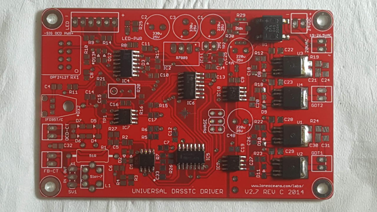
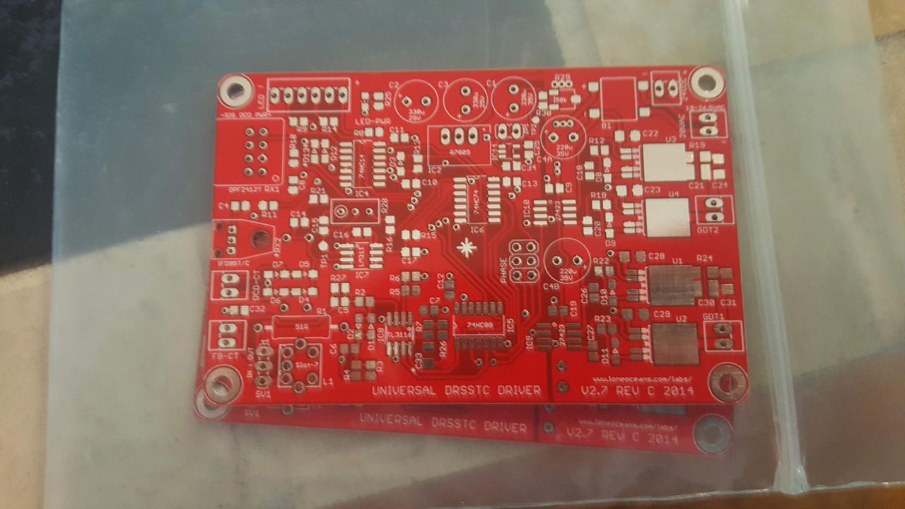
Controller Board
I finally got the controller board done. It is based on Steve Ward’s universal driver 1.3, but it is modified slightly. The schematic is the same, but I made the PCB more suitable for the Toner Transfer Method for PCB manufacture. A note on PCBs: don’t use Ferric Chloride! It is terrible for the environment. Use copper chloride instead.
- Controller PCB - Cadsoft Eagle Board File (Error Fixed 7/11/12)
- Toner Transfer - PDF file to print on a laser printer
- Parts List - TXT file with a basic parts list
I would suggest looking over this instructable for an idea how to use Eagle. For some reason whenever a board file is saved, the polygon doesn’t show up when you reopen it. If you want to edit the board, make sure you use the Ratsnest button to show the GND planes. If you just want to straight copy the board, you can use the transfer page. It is just a pdf file with two copies of the top and bottom of the board to be used in the Toner Transfer Method. The parts list is the same (nearly) as Steve Ward’s. Some of the parts are obsolete so you might have to substitute. I will try and post a copy of the order I placed with Mouser.
Simulations
Scan Tesla was developed by Terry Fritz in order to simply simulate a tesla coil (both solid state and original) using lumped circuit elements. Basically you just input the possible dimensions of your coil (secondary and primary inductance, tank capacitance, etc.) and Scan Tesla runs through each possibility and spits out the best one. Pretty neat software I must say. So anyway, here is the input text file and here is the output I get. I ended up winding 43.75" before running out of space. That works out to be about 3000 turns of wire. Quite a bit higher than you usually see. Scan tesla suggested that the benefits of a higher inductance outweighed the increase in resistance. I guess we will see… I measured the resistance of the wire using a standard digital multimeter. The inductance calculator I used suggested that my resistance should be around 1300 ohms. It was 289 ohms. Something is wrong here. Maybe the inductance calculator includes some reactance from the inductor as well? They do ask for the design frequency which would suggest they did. I am hoping that 289 ohms is right. My output drops significantly if the secondary resistance is 1300 ohms, obviously. The expected resistance for 27 AWG wire is about 51 ohms per thousand feet. That gives about 315 ohms resistance total. Much closer to what I measured. Skin depth is greater than the conductor diameter (below 130 KHz anyway).
I might try and modify Scan Tesla to include some practical design considerations. If you want to find the ideal number of turns in your coil you have to run separate simulations because secondary resistance and inductance are not linked. The program would just use the lowest resistance and highest inductance. Hardly a real world situation.
IGBTs
I am using the IXYS 60N60C2D1 brick IGBT. A lot of people say that it is underpowered for DRSSTC work, but it was cheap and still available on Mouser. It isn’t that hard to adapt a system to a different IGBT if I want to upgrade later. I ran into this article on IGBTs. It is a great read and very helpful. I would suggest at least browsing through it.
Gate Driver Transformers
The HvWiki on GDTs is very helpful. Check thedatastream.4hv.org link at the bottom of that page for some more info on GDTs. So now that I have an IGBT, I can start calculations on the GDT. I choose to use B64290L618X38 toroidal ferrites from Epcos. Probably should buy the next size up to increase the cross sectional surface area, but they work for now.
- Drive Voltage = 12V
- Frequency = 67.7 KHz
- AL = 10,700 nH/N2
- XSA = 51.26 mm2
This means that I need more than 8.3 turns to avoid saturation. With 10 turns… The inductance is 1.07 mH. The magnitizing current (rms) is 48 mA. The gate current is 13 mA. The total current a driver must supply is 61 mA.
10 June 2012
For those of you who have been doing these kinds of projects you know what happens when you really get into one. Everything else just kinda falls by the wayside. Unfortunately for you this means that I don’t update the site all that often. I do however have a few websites that you should read up on.
- Goodchild Engineering - Electrical Engineering student at ASU. Lots of good pics.
- Simulated Reality Systems - Very detailed intro to designing a DRSSTC.
- Chester’s Electronic Labs - An example of Steve Wards original driver.
15 May 2012
So I built my first DRSSTC in the past few weeks. I had to do a final project for my PHSX 536: Electronic Circuit Design and Measurement class. I didn’t choose a wimpy LED flasher circuit or anything like that…. I chose a Dual Resonant Solid State Tesla Coil. In retrospect, probably not something that should be done in a few weeks. It never officially worked. While taking some voltage measurements one of the 40n60 IGBTs blew up in my face. Scary… but no permanent damage. I wrote a nice paper on it however. There might be some things wrong with it. I kinda had to BS a little about the things I didn’t understand. Hopefully my teacher doesn’t understand either and skips over those parts. You can read it to get a good understanding of the schematic I used. Thanks Steve!
5 May 2012
I didn’t get an internship this summer. :,( On the positive side, now I have nothing to do but everything I want to do. I made a list of things that I want to accomplish this summer. One of them is build an audio modulated DRSSTC with an arc length longer than I am tall (~6’). All my classmates told me to call them when it was finished. Of course I am going to show off!
Secondary
So I have an idea of the arc length that I want. I started browsing around to get an idea of the size I would need to achieve 6’. I again came to Steve’s website and his DRSSTC-2. So apparently I am looking at a secondary form size of between 6" and 8“. The local Home Depot sells 4 inch drain pipe (OD=4.215”). This definitely would not suffice. So I settled on the 8" cardboard concrete tube. I have seen multiple websites with various suggestions for aspect ratios. Most stick between 1:3 to 1:5. I will go for 1:4 because its in the middle. The 4Hv Wiki suggests a wire size between 22-28 AWG for an 8" form. I went with 27 AWG because that is what I could find surplus for a decent price.
- Diameter = 7.75"
- Length = 43.75"
- 27 AWG wire
- N = 3020 Turns
- L = 295 mH
- C = 17 pF
- fres = 71,190 Hz
Bibliography
Craven, Richard M., Ivor R. Smith, and Bucur M. Novac. 2017. “Significant Practical Features of Tesla Transformers.” https://dspace.lboro.ac.uk/dspace-jspui/handle/2134/28067.